Table of Contents
Operating System
An operating system (OS) is system software that manages computer hardware and software resources, acting as an intermediary between users and the computer.
Core functions:
- Process management – runs and schedules programs
- Memory management – allocates RAM to applications
- File system management – organizes data on storage devices
- Device management – communicates with hardware via drivers
- Security & access control – manages user permissions
Types of OS
The different types of OS are -
- Uni-programming OS
- Multi-programming OS
- Multitasking OS (Time Sharing)
- Multiprocessing OS
- Multiuser OS
- Real Time OS
- Embedded OS
- Handheld Device OS
Uni-Programming OS
An OS which allows only one program to be present in the main memory at a time.
Multi-Programming OS
An OS which allows multiple programs to be present in the main memory at a time. The number of programs allowed in the main memory at a time is called the degree of multi-programming.
Types of multi-programming OS -
- Non-preemptive - If a program runs on the CPU, then it can leave the CPU only when it wants. The OS can’t kick the program out of the CPU.
- Preemptive - If a program runs on the CPU, the OS can kick it out of the CPU to allow some other program to run.
Multitasking OS
An extension of Multi-programming OS in which processes are executed in a round-robin manner.
Multiuser OS
It is used on a Computer System which can be used by multiple users concurrently.
Multiprocessing OS
Used on computers with multiple processors (CPUs).
Types of multiprocessing OS -
- Tightly Coupled - All processes use the same main memory.
- Loosely Coupled - All processes have their own dedicated main memory.
Realtime OS
Works on real time data and event. Each process has a deadline. How this process deadline is managed depends on what type of Realtime OS the system has -
- Soft - Processes don’t need to adhere to the deadlines strictly.
- Hard - Processes need to adhere to the deadlines strictly.
Embedded OS
A miniature OS that is used on special-purpose devices (not general-purpose computers), e.g. - ACs, Fridges, Cars, Washing Machines, etc.
Handheld OS
OS used on hand-held devices like mobiles phones, tablets, hand-held consoles like Nintendo Switch, etc.
System Call
A system call is a method for programs to interact with the Operating System.
- Programs by default aren’t provided permissions to interact with the hardware directly. They instead rely on System Calls for this interaction.
- Such operations are usually “privileged operations” that only the Operating system can execute.
Dual Mode of Operation
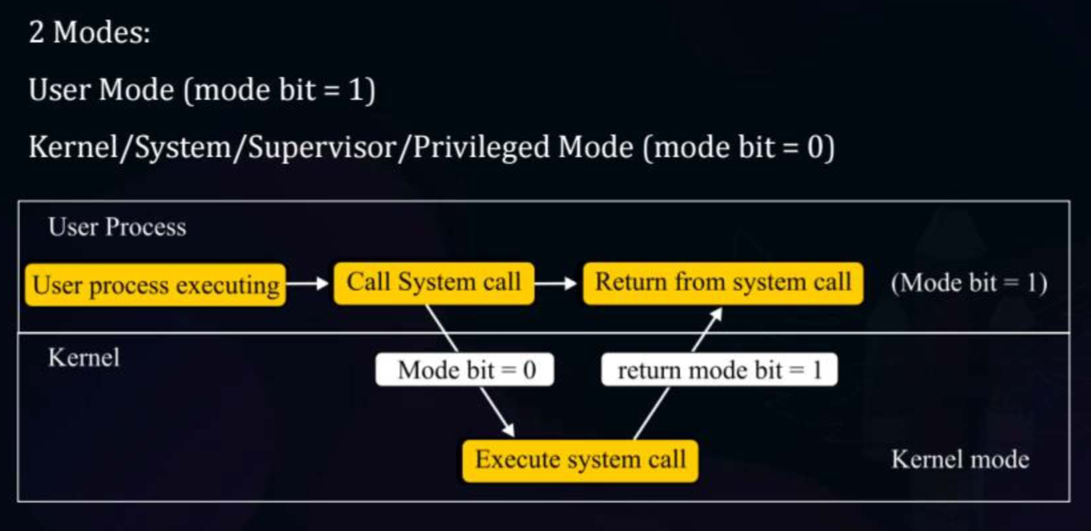
Operating systems need to protect themselves and system resources from faulty or malicious user programs. To achieve this, modern CPUs support dual mode operation — the hardware can run in one of two modes -
- User Mode - Programs run with restricted privileges and cannot access the hardware directly.
- Kernel Mode - The OS kernel runs here with full access to all hardware and instructions.
The mode bit is used to keep track of this mode. It is a single bit in the CPU’s status register (e.g., the PSW — Program Status Word) which indicates the current mode.
- 1 means User Mode
- 0 means Kernel Mode
Limited Direct Execution (LDE)
Modern operating systems virtualize the CPU using Limited Direct Execution (LDE):
- Direct Execution: The user program runs instructions directly on the physical CPU for maximum performance (no software interpretation overhead).
- Limited Control: Hardware + OS enforce strict privilege boundaries so user processes cannot execute restricted instructions, access unauthorized memory, or hog the CPU indefinitely.
System Call Hardware & Trap Mechanism
When a user process legitimately requires a privileged operation (e.g., reading disk or allocating device access):
- Syscall Register Setup: The process loads the designated system call number into a specific CPU register (e.g.,
%eaxin x86). - Trap Instruction: The process executes a trap instruction (e.g.,
int $0x80orsyscall), triggering a software interrupt. - Privilege Mode Switch: Hardware automatically switches the CPU mode bit from
1(User Mode) to0(Kernel Mode). - Trap Table & Syscall Table Lookup:
- CPU jumps to the pre-configured Trap Table / Interrupt Vector Table entry point (configured by OS during boot).
- The OS trap handler reads
%eax, indexes the Syscall Table, and dispatches control to the target kernel routine (e.g.,sys_read).
- Return-from-Trap: After completing the service, the OS executes a
return-from-trapinstruction (e.g.,iretorsysret), which restores the mode bit back to1(User Mode) and resumes process execution.
CAUTION
If a process attempts to execute a restricted/privileged instruction directly in User Mode without using a system call, the CPU hardware raises a trap/exception, and the OS forcibly kills the process.
Timer Interrupt Mechanism
To prevent a user process from running forever and hogging the CPU, the OS relies on a hardware timer.
- Hardware generates periodic timer interrupts (e.g., every 10ms from the CPU or a separate chip).
- User processes CANNOT mask or disable the timer interrupt (it’s a privileged operation).
- The dispatcher counts timer ticks between context switches. For example, if a process gets a 200ms time slice, that equals 20 ticks of a 10ms timer.
- Common time slices range from a few milliseconds to tens of milliseconds. In modern research systems, it can be as low as ~5 microseconds.
Hardware Support Required for Preemption and LDE
For the OS to preempt a running user process and regain control securely without process cooperation, five essential hardware features are required:
-
Dual-Mode Operation & Mode Bit:
- CPU must support at least two execution privileges: User Mode (
mode bit = 1) and Kernel Mode (mode bit = 0). - Critical instructions (modifying timer frequency, masking interrupts, modifying page tables) are privileged and can only execute in Kernel Mode.
- CPU must support at least two execution privileges: User Mode (
-
Periodic Hardware Timer & Unmaskable Interrupts:
- A hardware timer (on-CPU or dedicated chip) generates an interrupt at regular intervals (e.g., every 10ms).
- The user program cannot disable, mask, or reset this timer in User Mode, ensuring the OS periodically and unconditionally regains control of the CPU.
-
Atomic Hardware State Saving (PC & Status Registers):
- When an interrupt/trap occurs, the CPU hardware automatically and atomically pushes the Program Counter (
PC), Stack Pointer (SP), and Program Status Word (PSW/ flags) onto the process’s per-process kernel stack before switching to Kernel Mode and jumping to the handler. - This prevents race conditions where the process’s exact instruction pointer would otherwise be lost.
- When an interrupt/trap occurs, the CPU hardware automatically and atomically pushes the Program Counter (
-
Trap Table / Interrupt Vector Table (IVT):
- The CPU provides hardware dispatch to a table of handler addresses configured by the OS at boot time.
- When an interrupt triggers, the CPU uses the interrupt vector to index the IVT directly.
-
Memory Protection (MMU / Base & Limit Registers / Page Tables):
- Hardware enforces address boundaries for every memory access.
- Prevents a rogue user process from overwriting the OS kernel memory, modifying the IVT, or corrupting other processes’ kernel stacks.
Parts of OS
- Kernel - The core of the OS. Runs in kernel mode and manages everything — CPU, memory, devices, and processes. All other parts depend on it.
- Shell - The interface for users to interact with the OS — either a CLI (bash, cmd) or a GUI (Windows, macOS desktop).
Program vs Processes
Program
- A static set of instructions stored on disk (an executable file like
.exeor.out) - Just a passive entity — it does nothing on its own
- Exists in secondary storage
- One copy exists on disk
Process
- A program in execution (a “living program”) — an active, running instance.
- Consists of an instruction stream (sequence of instructions executing straight-line code, branches, loops) running within the context of a process state.
- Has its own address space, CPU register state, and OS resources.
- Exists in RAM.
- One program can spawn multiple processes (e.g., opening Chrome twice = 2 processes).
What is Process State?
Process State refers to everything that the running code can affect or be affected by:
- CPU Registers: Program Counter (PC), Stack Pointer (SP), General Purpose Registers (GPR), Floating Point Registers (FPRs), and Status/Flags (PSW).
- Address Space: The contents of memory allocated to Code, Data (
.data/.bss), Heap, and Stack.
.bss(Block Started by Symbol): Stores uninitialized global and static variables. To save disk space,.bsstakes up 0 bytes in the executable file on disk; the OS allocates zero-filled memory for it when loaded into RAM.- I/O & OS Metadata: Open file descriptors, allocated devices, and per-process OS management data.
Types of processes -
- CPU Bound - Process is intensive in terms of CPU operations
- IO Bound - Process is intensive in terms of IO operations
A Process can be thought of as a data structure with four components to it -
- Definition
- Representation/Implementation
- Operations
- Attributes
Process Definition
The program or the set of instructions for that process are its definition
Process Representation
Each process is stored in memory in four main sections -
- Code (text) section - Contains program instructions (typically read-only).
- Data section - Stores global and static variables:
.datasegment: Stores initialized global and static variables..bsssegment: Stores uninitialized global and static variables (zero-filled at startup).
- Heap - Dynamically allocated memory at runtime (via
malloc()/new). - Stack - Stores function activation records, local variables, function parameters, return addresses, command-line arguments (
argc,argv), and environment variables.
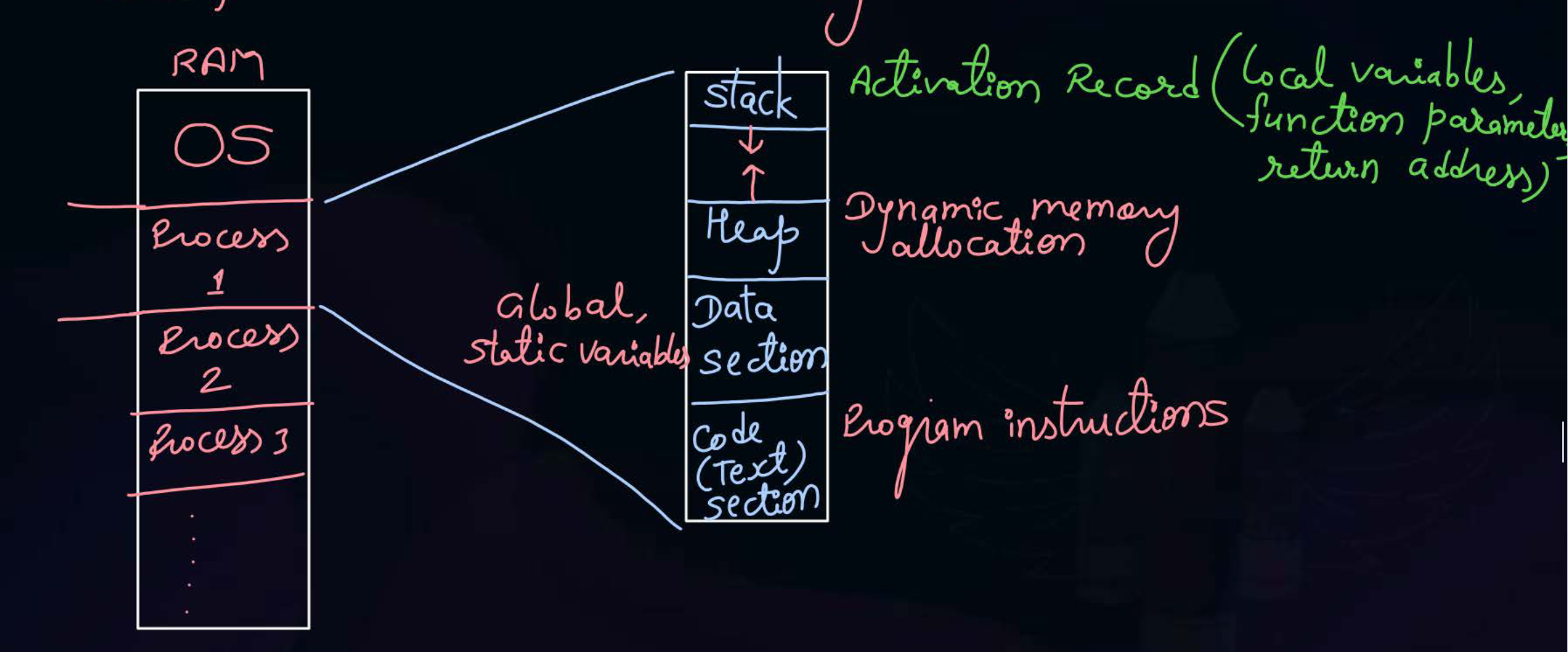
The code section and data section are of fixed size, while the heap and stack are of dynamic size.
- The additional space between the stack and the heap represents the extra memory both have access to.
- There exists a logical divider which signifies which portion is the heap and which portion is the stack, so neither can grow indefinitely.
- If either the stack or heap grow to such sizes that they intrude into each other’s area, that’s an overflow. Either a stack overflow or heap overflow.
Process Operations
Actions performed by the OS to manage processes.
Main operations:
- Create: New process is created (e.g.,
fork,exec) - Terminate: Process finishes or is killed
- Suspend: Temporarily paused
- Resume: Continued after suspension
- Block/Wait: Waiting for I/O or event
- Wakeup: Moves from waiting → ready
- Context Switch: CPU switches between processes
Purpose:
- Control execution and resource usage of processes
There are two fundamental paradigms to create a new process:
1. Build from Scratch
- Steps: Load code and data into memory Create an empty call stack Create and initialize the PCB (making it look like it’s re-entering from a context switch) Put the process on the ready list.
- Advantage: No wasted work.
- Disadvantage: Complex setup. You must specify all options explicitly (permissions, I/O destinations, environment variables). For instance, the Windows
CreateProcess()function takes 10 arguments.
2. Clone and Mutate (Unix Model)
fork(): Clones the calling process. It stops the current process, copies its code, data, stack, and PCB, and adds the new PCB to the ready list.exec(char *file): Overlays or replaces the current code and data segments with those from the specified executable file.- Advantage: Flexible and highly simple for users.
- Disadvantage: It is wasteful to copy everything and then immediately overwrite it. However, modern systems solve this using Copy-on-Write (CoW).
Let’s consider a common shell implementation pattern using fork and exec:
while (1) {
    char *cmd = getcmd();
    int retval = fork();
    if (retval == 0) {
        // Child process: setup environment, I/O, signals
        exec(cmd);  // exec does not return if it succeeds
        printf("ERROR: Could not execute %s\n", cmd);
        exit(1);
    } else {
        // Parent process: wait for child to finish
        int pid = retval;
        wait(pid);
    }
}
Process Attributes
The PCB (Process Control Block also known as process descriptor) is used to store the various attributes corresponding to any OS process.
- The OS keeps the PCB for every process with it for process management + context switching.
- OS saves/restores process state using PCB.
- The content of the PCB of a process goes into the CPU registers to run that process.
Some attributes stored in the PCB are -
- PID (Process ID) - Unique identifier for each process.
- PC (Program Counter) - Address of next instruction to execute.
- SP (Stack Pointer) - Address of current top of the stack.
- Registers (GPR, FPR, PSW) - General Purpose, Floating Point, and Status register values saved/restored during context switch.
- List of Devices - Devices allocated
- Type - Process category
- Size - Memory required by the process
- Memory Limits - Boundaries of address space
- Priority - Scheduling importance
- State - Current status (new, ready, running, waiting, terminated)
- List of Files - Open files and file descriptors associated with the process
Let’s look at a concrete example of a PCB structure from the xv6 operating system:
struct proc {
    char *mem;              // Start of process memory
    uint sz;                // Size of process memory
    char *kstack;           // Bottom of kernel stack for this process
    enum proc_state state;  // Process state
    int pid;                // Process ID
    struct proc *parent;    // Parent process
    int killed;             // If non-zero, have been killed
    struct file *ofile[NOFILE]; // Open files
    struct inode *cwd;      // Current directory
    struct context context; // Switch here to run process
    struct trapframe *tf;   // Trap frame for current interrupt
};
And its corresponding context structure:
struct context {
    int eip;  // Instruction pointer
    int esp;  // Stack pointer
    int ebx;  // Base register
    int ecx;  // Counter register
    int edx;  // Data register
    int esi;  // Source index register
    int edi;  // Destination index register
    int ebp;  // Stack base pointer
};
The process states defined in xv6 are: UNUSED, EMBRYO, SLEEPING, RUNNABLE, RUNNING, ZOMBIE.
Context Switching
The values stored inside the PCB are referred to as the context of that process.
- The method of bringing the context of a process to the CPU and switching it with the existing context is called as context switching.
This requires specific hardware support because values such as the Program Counter and Instruction Pointer may change if we were to rely on a set of instructions for context switching, thus resulting in an invalid save.
The context switch involves a two-level save and restore mechanism:
- Level 1 (Hardware-level): When a timer interrupt occurs, the hardware automatically saves process registers (like PC and PSW) onto the process’s per-process kernel stack (k-stack). It then switches to Kernel Mode and jumps to the trap handler.
- Level 2 (OS software-level): The OS trap handler calls a
switch()function. This function saves the kernel registers from Process A into A’s PCB, restores Process B’s kernel registers from B’s PCB, switches to B’s kernel stack, and finally executes areturn-from-trapinstruction. The hardware then uses this to restore B’s user registers from its k-stack and jump to B’s instruction pointer.
Notice how this relies on a key insight: Each process conceptually has its own per-process kernel stack and its own per-process kernel thread.
Process States
The current activity the process is performing.
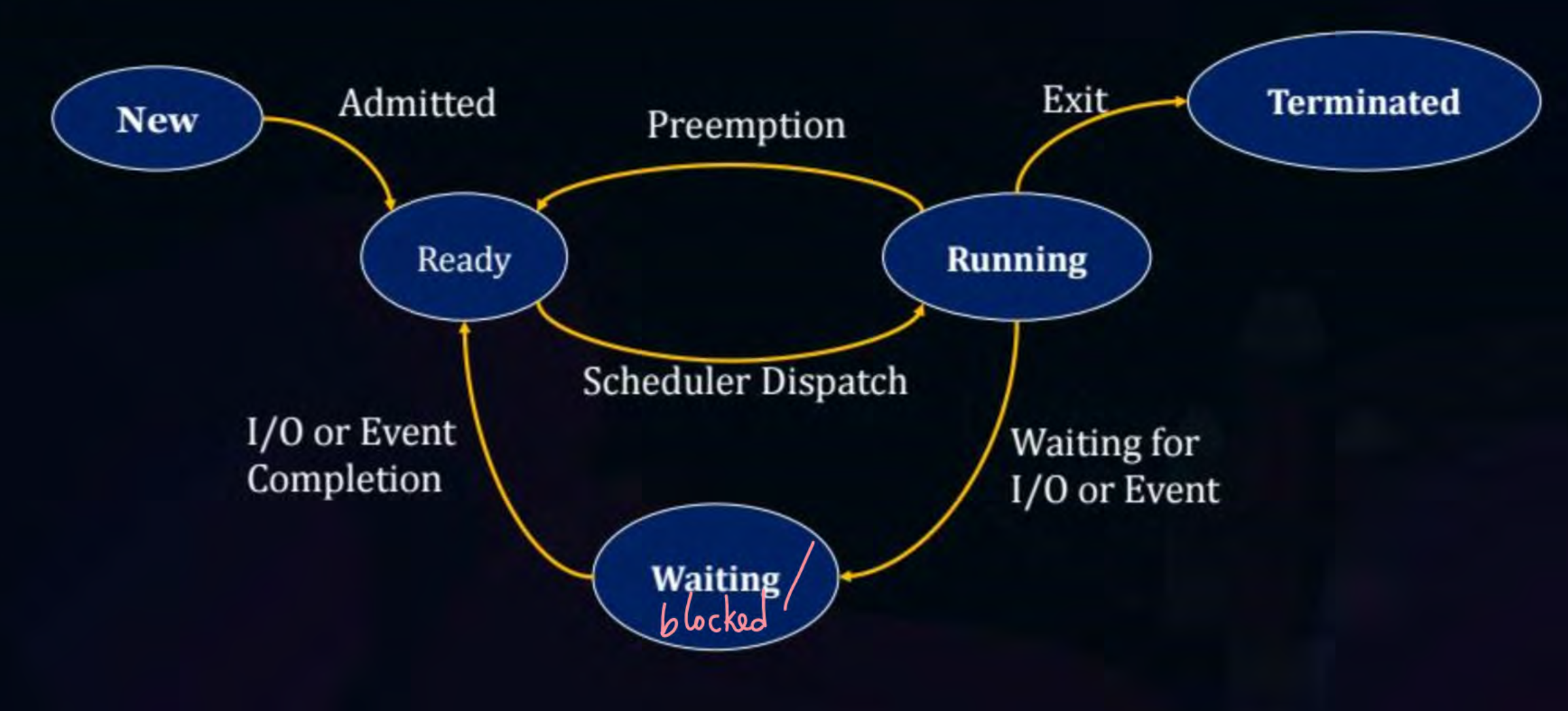
The states of a process are -
- New - All installed processes. (Not in memory yet)
- Ready - All processes which are waiting to run on CPU. (Brought to memory)
- Running - All processes running in the CPU.
- Blocked - All processes which are waiting for an I/O or event.
- Terminated - A completed process (Removed from memory)
When dealing with multiple processes in Multiprogramming or Multitasking OS we need to schedule the processes to run one after another.
- The scheduler is a component of the OS that selects which process to run on the CPU.
- The dispatcher is a component of the OS which performs context-switching (brings and kicks processes from the CPU).
State transitions -
- New - Only Ready.
- Ready - A scheduler will run this process, thus making its state as Running.
- Running - By itself it can only go to Terminated or Waiting.
- If the OS is preemptive, then due to preemption it can go to Ready as well.
- Waiting - Only upon receiving an I/O or event will it move back to Ready.
- Terminated - None
Scheduling Queues and Scheduler
Scheduling Queues keep processes in certain states -
- Job Queue - All processes which are in new state are kept here
- Ready Queue - All processes which are in ready state
- Device Queue (or Event Queue) - All processes which are kept in waiting state. Importantly, there is one logical queue per event type (e.g., a disk I/O queue, a lock wait queue, a network queue). Each contains all processes waiting for that specific event to complete.
Schedulers -
- Long-Term Scheduler (Job Scheduler) - Brings a process from new state to ready state
- Short-Term Scheduler (CPU Scheduler) - Selects one of the ready processes to run on CPU
- Mid-Term Scheduler (Medium Term) - Responsible for freeing up space in your memory to allow for new processes, in cases where the memory is fully utilized.
- The PCB for this process stays in the memory with the OS, just the process itself is removed from the memory and sent to the secondary memory. This functionality is called swapping out.
- Once the main memory again has enough space, the swapped out process is brought back from the secondary memory to the main memory. This functionality is called swapping in.
- Only processes in Ready or Blocked state are swapped out.
Updated process state transition diagram -
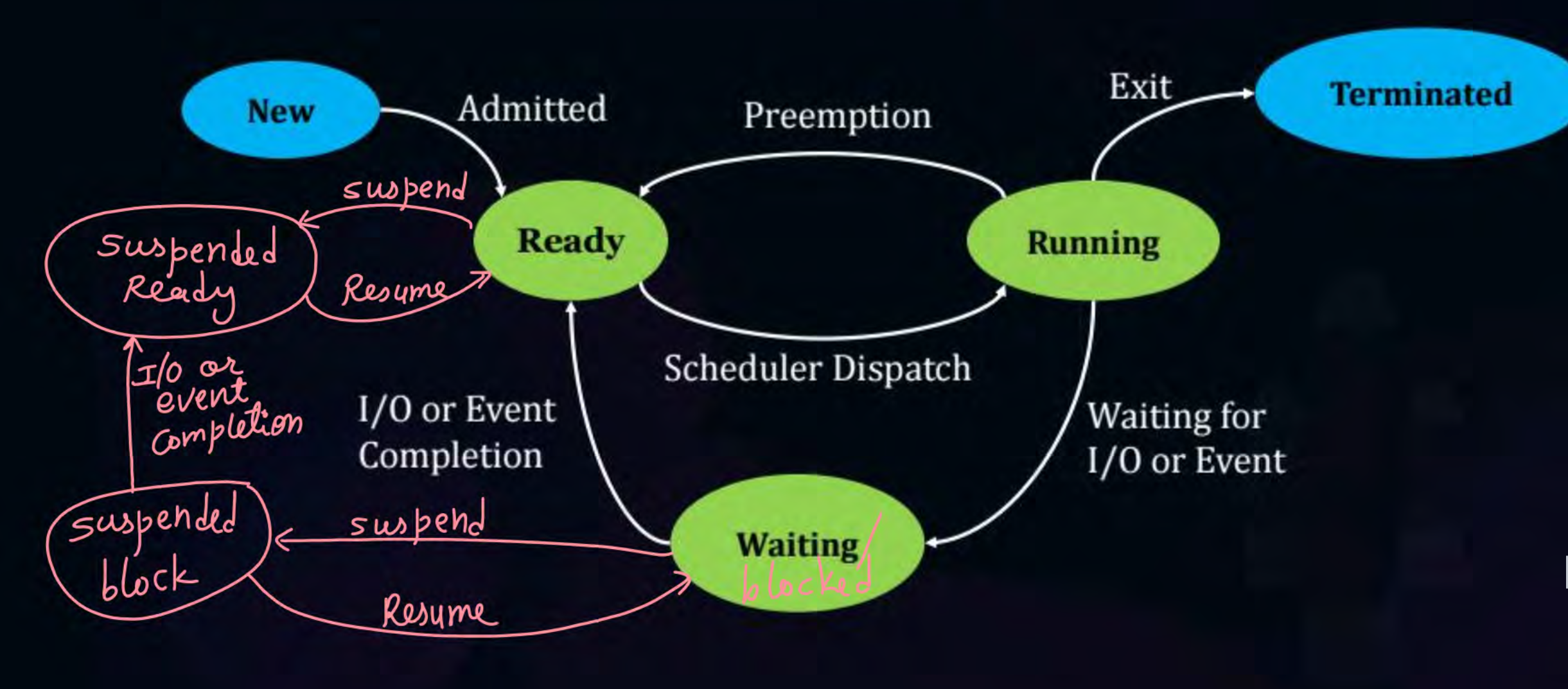
New states -
- Suspended Ready - Processes in Ready state that are swapped out enter this state.
- Suspended Block - Processes in Waiting/Blocked state that are swapped out enter this state.
Degree of Multi-Programming for Schedulers
- Long-Term Schedulers - Because it brings processes to the memory, it increases the degree of multi-programming.
- Short-Term Schedulers - It doesn’t bring or remove processes from the memory, thus it doesn’t affect the degree of multi-programming.
- Mid-Term Scheduler (Medium Term) - Because it both removes and brings processes to the memory, it can increase and decrease the degree of multi-programming.